How a cable system works.
Two components determine the safety of a suspension: the gripper and the cable. This is how they work and how we rate them.
The gripper
Inside the body, three or six steel balls surround the cable. A spring pushes them against an inner cone: when the load pulls down, the balls bite into the cable and lock it. Upwards, the cable runs free. Pressure is spread around the cable without crushing it.
- Feed the cable through the plunger until it passes through the mechanism.
- Slide the gripper to the required height: it locks by itself when released.
- To lower or readjust, press the plunger with a finger, move and release.
- Leave about 25 mm of cable beyond the mechanism for readjustment; if trimmed, never less than 12 mm.
- The cable must enter and leave the gripper within 5° of its axis.
- An inclined cable carries less load than a vertical one: see the angle table.
- Never use the cable as an electrical conductor or push the surplus into electrical boxes.
The 7×7 cable
Seven strands of seven galvanised or AISI 304 stainless steel wires. Compared with 7×19, with finer wires, 7×7 is stiffer, hangs straight and its thicker wires are not crushed by the balls: the grip is more reliable. It is the right cable for static loads; 7×19 is reserved for moving cables or large diameters.
A gripper holds approximately 60% of the cable's breaking load. That is why we rate the working load on the combination, not on the cable alone: cable breaking load × 0.6 ÷ 5.
| Ø mm | Breaking load galv. | Breaking load stainless | Working load galv. | Working load stainless |
|---|---|---|---|---|
| 1.0 | 85 kg | 75 kg | 10 kg | 9 kg |
| 1.2 | 120 kg | 108 kg | 14 kg | 12 kg |
| 1.5 | 180 kg | 170 kg | 21 kg | 20 kg |
| 2.0 | 310 kg | 290 kg | 37 kg | 34 kg |
Minimum cable breaking load according to manufacturer data. Working load = breaking load × 0.6 ÷ 5, static load and vertical cable. Indicative values, pending validation in our laboratory for each combination.
Neodymium magnets
A neodymium magnet inside a steel cup concentrates all its force on the contact face: a 25 mm magnet can hold around 20 kg in pure pull. But nominal force is measured under ideal conditions, and a significant part is lost on site.
- Thin sheet: below 5 mm of steel the force drops markedly.
- Paint, rust or dust separate the magnet from the steel and reduce the hold.
- Sideways the magnet slides: shear resistance is only a quarter of the pull, unless rubber-jacketed.
- Above 80 °C standard neodymium loses force permanently.
That is why our working load is at most one fifth of the force measured on real sheet steel – on our bench or on site – always in a vertical pull.
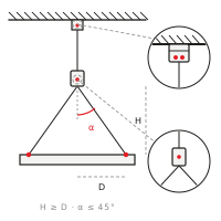
Inclined cables.
When the cable does not hang vertically, each cable carries less: the working load is multiplied by the cosine of the angle α. At 45°, 71% remains; at 60°, half. This applies to every 2-, 3- and 4-leg kit.
| α | Ø1.2 mm | Ø1.5 mm | Ø2.0 mm |
|---|---|---|---|
| 0° | 14 kg | 21 kg | 37 kg |
| 15° | 13 kg | 20 kg | 35 kg |
| 30° | 12 kg | 18 kg | 32 kg |
| 45° | 9 kg | 14 kg | 26 kg |
| 60° | 7 kg | 10 kg | 18 kg |
Rule H ≥ D: the vertical drop must be equal to or greater than the horizontal distance between the anchor and the panel point. The angle then stays within 45°. Never more than 60°.
Recommendations for use.
 Static loads only
 No chlorinated or corrosive environments
 No grease or lubricants
 Never use frayed cable
 Maximum 60° inclination
 Do not paint components
Have a project?
We help you choose the system and send data sheets, quantities and price.